The UK's transition to electric fleets is exposing a fundamental infrastructure constraint. Traditional single-unit DC chargers — designed for forecourt deployment — cannot scale to the density and power demands of modern fleet depots. A 50-bay bus garage drawing simultaneous multi-megawatt demand needs a different architectural approach entirely.
The answer lies in separating the two functions that every charging system must perform: power conversion (AC to DC) and power delivery (getting that DC to the vehicle). Bundling both into every charger made sense for single installations. At depot scale, it creates compounding cost and complexity.
The core insight: a fleet depot is not fifty individual charging events happening simultaneously — it is one large power management problem, with vehicles as the loads. The architecture should reflect that.
Why Single-Unit Chargers Don't Scale
Each traditional integrated DC charger bundles a power module, distribution switchgear, display, and communications into one cabinet. For a single vehicle, this is efficient. For a 50-bay depot, the problems compound:
- Cable trenching multiplies linearly. Every charger requires its own 150–300mm² cable run from the substation. In a large depot, this means 50 individual trenches, 50 duct banks, and 50 concrete surrounds — each at £800–1,200 per linear metre.
- Grid allocation is static. Power capacity equals connection count. A 150kW charger holds 150kW of grid allocation permanently — even when idle at 2am.
- Maintenance is disruptive. A single component failure (contactor, module, display) takes the entire unit offline. In a 50-bay depot, this is statistically guaranteed to happen daily.
- Upgrades require full replacement. When vehicle technology evolves — from 400V to 800V platforms, from 150kW to 350kW acceptance rates — every integrated unit must be replaced.
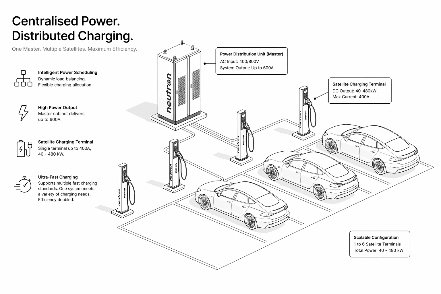
Centralised power architecture: one Master Unit manages conversion and distribution; lightweight Terminal Units handle vehicle connections at each bay.
The Group Charging Paradigm
Neutron's Master-Terminal architecture — pioneering what the industry now calls group charging — separates power conversion from power delivery at the hardware level. A single Master Unit handles all AC-to-DC conversion and power distribution management. Lightweight Terminal Units, distributed across the fleet depot charging layout, provide the physical connection point at each bay.
Terminals have no high-voltage electronics of their own. They carry less than 36V DC on their external surfaces — eliminating the live-current exposure risk present in every integrated charger. A technician can work on a terminal bay without isolating the entire system.
The topology scales cleanly:
| Master Unit | Terminals | Peak Capacity | Bay Coverage |
|---|---|---|---|
| 240 kW | 2–3 | 240 kW | 2–3 bays |
| 480 kW | 4–6 | 480 kW | 4–6 bays |
| 960 kW (×2 masters) | 8–12 | 960 kW | 8–12 bays |
| 4 MW (11kV MV direct) | 20+ | 4,000 kW | 20+ bays |
Dynamic power pooling means the total installed capacity serves all connected vehicles simultaneously — but allocates current based on real-time state of charge. A vehicle at 90% SOC receives minimum current; one at 20% SOC receives maximum. The system dispatches intelligently, without operator input, 24 hours a day.
Engineering Advantages: Excavation and Civil Works
The civil engineering savings are where group charging architecture delivers its most immediate ROI. Where conventional depot build requires one cable run per bay, Master-Terminal consolidates:
- One high-capacity feed per Master serves 2–6 bays. A 480kW Master connected to 6 terminals requires one cable run — not six.
- Low-voltage interconnects from Master to Terminal use simple, flexible conduit rather than heavy armoured cable. An installation team can complete a 6-bay cluster in a single working day.
- Terminal variants eliminate ground disruption. Ceiling-drop terminals (installed on gantry or ceiling beams), in-ground pop-up terminals (V2 rated to IP68), and wall-mount terminals serve the same Master without requiring trench access at each bay.
The PDU (Power Distribution Unit) switching architecture underpins these reliability gains. Unlike matrix or relay-based designs, PDU topology presents the lowest DC arc risk, highest system stability, and simplest maintenance profile — critical in depot environments where uptime is an operational requirement, not a nice-to-have.

The Neutron 480kW Master Unit: AC input, 50–1000V DC output, managing up to 6 terminal bays with dynamic load balancing and OCPP 1.6J integration.
2025: The 4MW Threshold
In 2025, Neutron extended the Master-Terminal concept to its logical limit. An 11kV medium-voltage, 4MW integrated full-matrix ultra-charger — not an incremental upgrade but a new category — reached commercial deployment.
Six new products launched in 2025, filling gaps that no manufacturer had previously addressed:
The 4MW system connects directly at 11kV medium voltage — bypassing LV distribution entirely and eliminating the transformer losses and capacity constraints that limit conventional depot installations.
| Specification | Value |
|---|---|
| Grid connection | 11kV medium voltage direct |
| Total system output | 4,000 kW |
| Single-gun maximum | 2,000 kW |
| Dual-gun maximum | 4,000 kW |
| Voltage range | 200–1,500V DC |
| Compatible connector | MCS (Megawatt Charging System), CCS2, CHAdeMO |
| Charge time — 400kWh heavy truck | ~10 minutes |
Oil-Electric Parity for Heavy Fleets
The 10-minute charge time for a 400kWh new energy heavy truck is the benchmark the logistics and haulage industry has been waiting for. A commercial diesel fuel stop — pump, pay, go — takes 8–12 minutes. The 4MW system matches that exactly.
This is what oil-electric parity looks like in practice: not just energy equivalence, but matching diesel refuelling speed. A driver doesn't change their behaviour. A depot operator doesn't rebuild their shift pattern. The charging infrastructure adapts to the fleet, not the other way around.
For heavy truck operators, the combined case is compelling:
- A 20-bay heavy depot drawing 4MW peak can charge its entire fleet in a standard overnight window
- 10-minute daytime top-ups eliminate range anxiety on long routes without dedicated en-route charging
- Liquid-cooled megawatt terminals handle sustained 2MW output without thermal throttling
Grid Integration: From Load to Asset
The 2025 architecture goes beyond vehicle charging. With VPP (Virtual Power Plant) integration built into the charge management platform, a fleet depot becomes a dispatchable grid asset.
During periods of peak grid demand, parked and fully-charged vehicles can export energy back to the network — with the Master-Terminal system managing bi-directional flow automatically within OCPP and OCPI frameworks. A 100-vehicle bus depot with 60% fleet availability at any given time holds approximately 12,000–18,000kWh of stored energy: equivalent to a medium-scale grid battery, available on 15-minute notice.
Under the UK's flexible export tariffs and Demand Flexibility Service, this stored capacity can generate revenue that partially offsets charging infrastructure operating costs — converting a pure cost centre into a partial revenue stream.
Zero-carbon campus architecture extends this further: solar PV, battery storage, EV fleet, and building loads managed as a single optimised system, with the group charging platform as the intelligent hub.
Phased Deployment Path
No depot needs to commit to 4MW from day one. The Master-Terminal architecture supports a phased build-out in which each investment is additive rather than replacement:
Phase 1 — Pilot cluster: 240 kW
One 240kW Master + 3 terminals. 3 bays active. Validates grid connection, civil works, and driver workflow. Can be live in 7–10 days from grid approval.
Phase 2 — Expanded fleet: 960 kW
Add second 480kW Master + 3 terminals. 6–8 bays active. Existing Phase 1 terminals connect without modification.
Phase 3 — Full depot: 1.92 MW
Four 480kW Masters, 20–24 terminals. Full bus or logistics fleet coverage with dynamic load balancing across the site.
Phase 4 — Heavy fleet / MV direct: 4 MW
11kV medium-voltage connection, liquid-cooled megawatt terminals. Heavy trucks, coaches, and high-demand applications. Oil-electric parity achieved.
Each phase is backwards compatible. Existing terminals connect to upgraded Masters without replacement. The civil works done in Phase 1 support the full Phase 4 system.
Design Your Depot Architecture
Neutron provides free depot assessments covering DNO capacity analysis, parking layout, load modelling, and phased investment planning — with no obligation to proceed.
Request a Free Assessment